About the Project
Using a LaCrosse Rain Gauge Model TX58UN-IT (or similar) with a micro controller (ESP32, Arduino, Electric Imp). The existing circuit board that transmits to a LaCrosse Weather System is not used. This describes how to add external wires that you can attach to a micro controller to count the pulses as the rain gauge tipper operates. I selected this particular gauge because I knew it had a traditional glass magnetic switch inside. This is easy to isolate and solder wires to each end of the switch.
Dissassemble Gauge
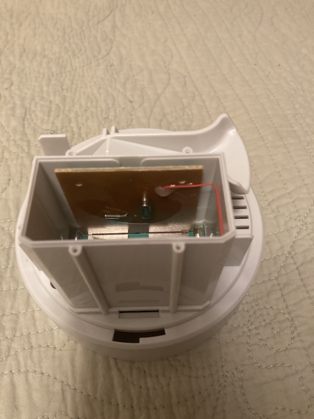
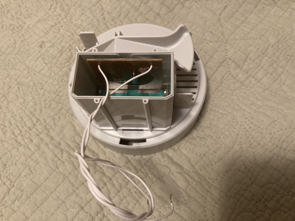
Open the gauge by twisting the outer rain collector can. Remove the 4 screws on the white rectangular cover. You'll see the circuit board assembly inside.
Lift Out Circuit Board
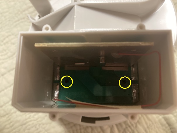
There are 2 black screws on the bottom of the board assembly. Remove them and lift out the assembly. It will come out with the component board and battery board. These are connected together in one assembly.
Identify the Magnetic 'Reed' Switch
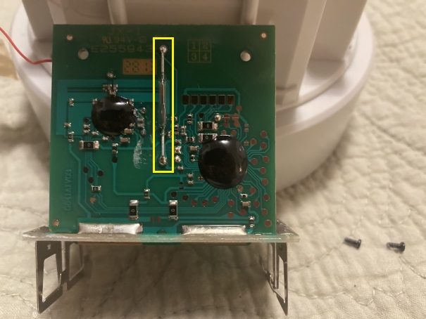
The only part on the circuit board we are interested in is the Magnetic Reed Switch. This glass switch "closes", or makes continuity, when the tipper magnet passes over it.
Connect Wires
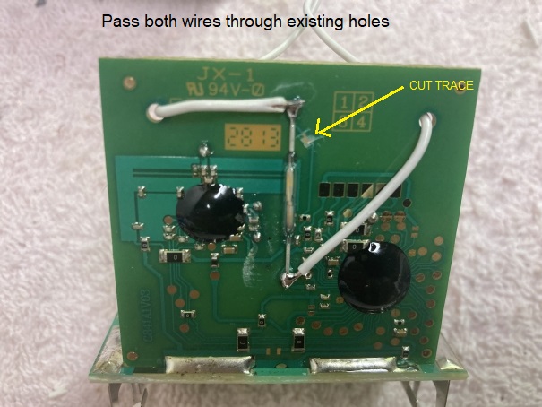
Connect 2 small wires to each end of the switch. Notice that you can cut the circuit board trace with an X-acto knife to isolate the switch from anything on the circuit board. If the board trace remains, it is possible some other resistor or diode on the board might affect our switch continuity. Remember, we don't care about any other components on the board. I've already cut and threw away the antenna too.
Re-Install the board
Put the board assembly back into the gauge. The wires are passed through the existing holes on the circuit board. With a multi-meter, you can measure ohms (or continuity) on the wires. The wires should read "open" until the tipper magnet passes over. Tip it back and forth and see the indication on your meter.
Using the Device
Now you can find a place to pass the wires from inside the rectangle box to another part of the gauge. Any holes you drill to pass these wires through, use RTV or glue gun to seal the hole from moisture. I used a 50 foot multi-conductor cable (22 ga) and ran it to an existing controller box I am using for my deck lights. In my case, I'm using an Electric Imp (IMP003) micro controller. You could be using an Arduino, ESP32, or any other micro controller.
You may also choose to slip an ESP32 right inside the box and run power to the gauge using a cable or build some sort of solar charger with LIPO batteries. I use an IMP003 controller because I like the secure WiFi connection and the Electric Imp Agent Cloud Service. Since I already have a plastic box outside my house (for my patio deck lights), I'm just using an unused I/O Digital Input Pin "tied high" and when the tipper flips, it makes the Pin LOW and is debounced by the controller software.
Each pulse is counted and the program adds the pulses. Every 5 minutes it sends the tipper count to a database on my website. Each entry is time-stamped. If there are no pulses counted in the 5 minute interval, no data is sent. With Google Charts and PHP scripting, I grab the online data and generate several rain gauge charts. I can also have a text message sent to my phone when the first tip occurs to let me know it is raining. I wanted to know what the official specs were in regards to amount of water per tip. I emailed LaCrosse for information and they did not get back to me until a week later. By then I had already figured it out. They verified that the specs are "10 tips should equal .10 inches". That would be .01 inches per tip.
Calculating and Calibrating the tipper
So now I already know that each tip is .01 inches of rain, since LaCrosse emailed me back. I will describe the calibration process anyhow because you might have a gauge that has an unknown amount per tip. So let's pretend that I don't know what the tip amount is ...
The diameter of the collection funnel (which is round) is 4.4 inches.
Because science and medical uses Metric, I will use Metric. My medicine dropper is in milli-liters (ml).
4.4 inches (round) has an area of 98.10 square centimeters.
I'll pick a nice even number to start with (10ml).
10ml / 98.10 = 0.1019368 cm of depth (of rain) for that collection funnel size.
In millimeters that is 1.019368 mm. ... In inches that is 0.04 inches.
I used my dropper syringe to determine that the bucket tips at exactly 2.5ml of water.
This took a lot of trial and error. Making sure I checked the tipper both ways and with many tests.
It's just by luck that I picked 10ml and the bucket tips at 2.5ml ... that made the math easy.
10ml of water in a 4.4 inch cylinder will result in a depth of 0.04 inches of water ...
4 tips (at 2.5ml each) = 10ml.
Therefore, each tip of the bucket is 0.01 inches.
I have to assume that LaCrosse deliberately made the funnel 4.4 inches and the tipper is .01 inches per tip. I would guess all tipper gauges have some sort of specific calibration similar to LaCrosse.
When the bucket tips and spills out the water, it left some of the water in the tipper (several drops). I felt this might make the gauge less accurate. Example, it might take 2.6ml to tip the bucket. I'll compare accuracy to a traditional manual 'more professional' rain gauge. I may have to adjust the calibration factor.
After a few days ...
We had significant rain (1.85 inches) over two days. So far, with my use of .01 inches per tip, I compared my tip count with my accurate "old fashioned" rain gauge and it's only off by .02 to .04 inches, depending on when I read it. That's really good. It all depends on if I read it right before or after it tips, and my accuracy in reading and emptying the old hand dumping gauge might also cause some error. I would really be happy with an error factor of 1 tenth ... .04 is even better.
Charting data using Google Charts
My Electric Imp003 microcontroller has a 5 minute loop timer. It always looks for a "tip" on the gauge (debounced digital input). It counts the tips and every 5 minutes it uploads the tip count to my website (only if the count > 0). It then resets the tip count to zero. Each data point is timestamped. I use Google Charts (w/javascripting) to create charts.
This chart shows one complete day:
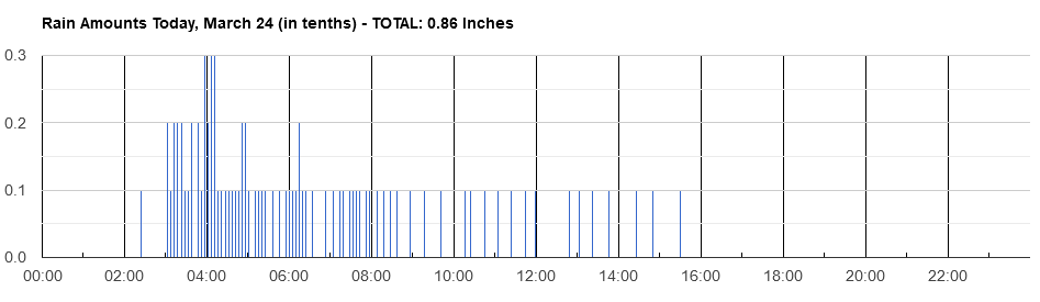
So there was heavier rain at 4am. The chart automatically scales. Currently showing in tenths, so .1 tenth is one hundreth. Another chart shows by the month, and a third chart shows the whole year. Clicking on any date shows the rain for that day.
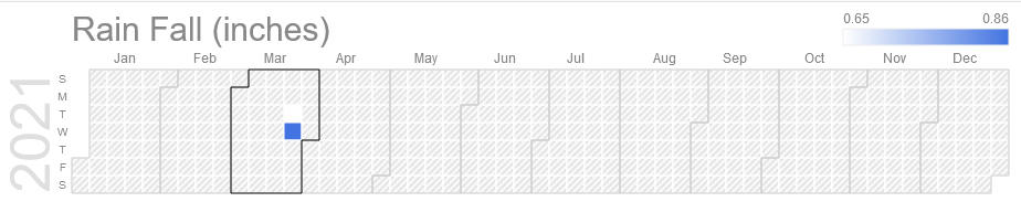
Here is the chart for the year ...
Click Here to See Actual Rain Gauge Current Data
Make sure the gauge remains level at all times ...
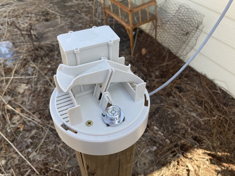
I glued-on a round spirit level (with a bubble) to make sure the gauge is properly level. If the post gets bumped or moved by anything, I can re-level if needed.
Mounted on a post
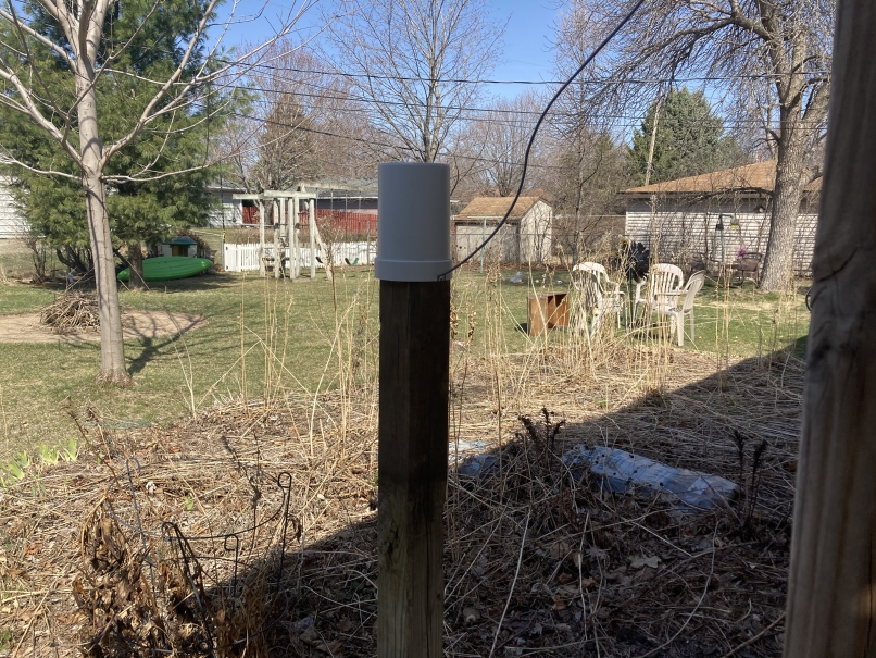
Mounted on a post high enough to where kids or animals can't mess with it. Low enough to where I can open it for inspection or cleaning.
This is the Electric Imp003
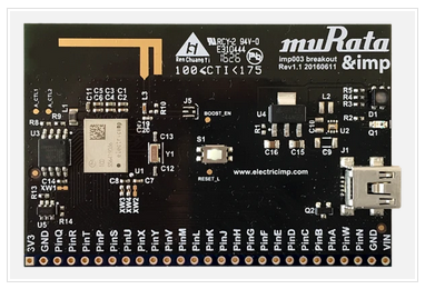
Just like an ESP32, you define the pins that you use, and programming is done on the Imp IDE (online). This device can be programmed and downloaded from anywhere in the world as long as it is connected to WiFi and is communicating with the Imp Agent. Data is secure and the proprietary connection between the Imp device and the Imp Agent (cloud) makes it more secure than an ESP32. But the down-side is the requirement to keep it connected to the Imp Agent, which is free for developers. I use my own website w/PHP to handle all of the data and website scripting. The Imp could host its own website (on the device), similar to the ESP32, but I am going to be storing a lot of data. These are programmed in a language called 'Squirrel', but is very similar to an ESP or Arduino device.
My outside deck/patio lights are controlled using the same Imp003 as the rain gauge. I just use pin-T for my rain gauge tipper switch. I programmed it as a digital input (tie-high). The device is event-driven, just like an Arduino. It always looks for a pin-T high-to-low level change and executes a function when that occurs.